- Document Solutions for Imaging Overview
- Key Features
- Getting Started
- Product Architecture
-
Features
- Create Image
- Load Image
- Save Image
- Work with GIF files
- Work with TIFF Images
- Work with ICO files
- Work with SVG Files
- Work with WebP Files
- Process Image
- Apply Effects
- Layouts
- Complex Graphic Layouts
- Tables
- Work with Image Colors
- Transparency Mask
- Work with Graphics
- Work with Text
- Work with Exif Metadata
- Render HTML to Image
- Render Using Skia Library
- Document Solutions Image Viewer
- Samples
- API Reference
- Release Notes
Layouts
DsImaging provides LayoutRect and other related classes in the GrapeCity.Documents.Layout namespace to place multiple elements on a PDF page or image without having to calculate positions of each element relative to other ones.
The LayoutRect and other related classes implement the flat layout model. There are no chains, barriers, guidelines, biases, or other complications. Certain features of the layout model are:
Rectangles can be rotated by a multiple of 90 degrees.
Constraints can reference anchor points from other views (with different transformation matrices).
Rectangle sides can be bound to arbitrary contours.
Views can be nested, and the inner view’s transformation is automatically recalculated when the outer view’s transformation changes.
LayoutHost is the main object, which defines the origin of the coordinate system. Also, this object performs layout when all other objects are prepared and linked. LayoutHost can create views. LayoutView defines a rectangular region with some width, height, and transformation, and the units of all sizes and coordinates are floats and can be of arbitrary dimension.
A LayoutHost can create multiple LayoutViews with different sizes and transformations, and each LayoutView can create multiple LayoutRects. A LayoutRect is a rectangle whose sides are parallel to the LayoutView sides. LayoutRect is defined by four points: P0, P1, P2, and P3.
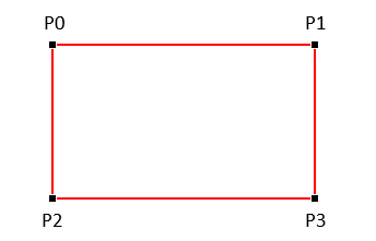
The layout engine calculates the exact positions of the P0, P1, and P2 points for each LayoutRect of each LayoutView within a LayoutHost. The size and position of a LayoutRect can be determined if some of the following parameters are known: Width, Height, AspectRatio, Angle (as a multiple of 90 degrees), Left, Top, Right, Bottom, HorizontalCenter, VerticalCenter. The Width, Height and AspectRatio parameters are assigned directly; however, other parameters are usually defined as an offset or delta from the LayoutView, other rectangles, or the special anchor points.
The transformation matrix is Matrix from the GrapeCity.Documents.Common namespace. It has double precision vs. single precision Matrix3x2 from System.Numerics. The Matrix can easily be converted to Matrix3x2, or it can be multiplied by a Matrix3x2.
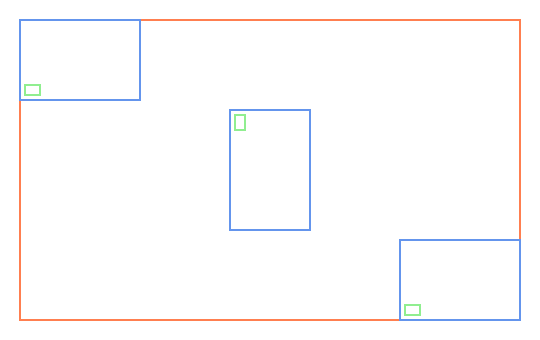
Refer to the following example code to draw a simple layout:
// Initialize LayoutHost. This defines the origin of the coordinate system.
var host = new LayoutHost();

// Create LayoutView. This defines a rectangular region with some width, height, and transformation.
LayoutView view = host.CreateView(500, 300, Matrix.Identity);

// Create lists for blue and green rectangles.
var blueList = new List<LayoutRect>();
var greenList = new List<LayoutRect>();

// Create LayoutRect. LayoutRect is a rectangle whose sides are parallel to the owner LayoutView sides.
LayoutRect rect = view.CreateRect();

// Set a constraint on the rotation angle of the LayoutRect.
rect.SetAngle(null, 90);

// Set width, height, and center point.
rect.SetWidth(120);
rect.SetHeight(80);
rect.SetHorizontalCenter(null, AnchorParam.VerticalCenter);
rect.SetVerticalCenter(null, AnchorParam.HorizontalCenter);

// Add the LayoutRect to the blue list.
blueList.Add(rect);

// Add a green LayoutRect to the blue LayoutRect.
AddGreenRect(rect);

// Add a tiny green rectangle at the bottom left corner of the blue rectangle.
void AddGreenRect(LayoutRect r0)
{
    var r1 = view.CreateRect();
    r1.SetWidth(r0, AnchorParam.Width, 0, 0.125f);
    r1.SetHeight(r0, AnchorParam.Height, 0, 0.125f);
    r1.AnchorBottomLeft(r0, 5, 5);
    greenList.Add(r1);
}

// Create two more blue rectangles and place them at different places in the LayoutView.
// Add green rectangles to the blue rectangles.
rect = view.CreateRect();
rect.AnchorTopLeft(null, 0, 0, 120, 80);
blueList.Add(rect);
AddGreenRect(rect);

rect = view.CreateRect();
rect.AnchorBottomRight(null, 0, 0, 120, 80);
blueList.Add(rect);
AddGreenRect(rect);

// Calculate all rectangle coordinates based on the constraints provided.
host.PerformLayout();

// Draw the rectangles on a bitmap.
using var bmp = new GcBitmap(540, 340, true);
using (var g = bmp.CreateGraphics(Color.White))
{
    var pen = new Pen(Color.Coral, 2);

    // Set the transformation matrix of the LayoutView when creating the view.
    var m = Matrix3x2.CreateTranslation(20, 20);
    g.Transform = view.Transform.Multiply(m);

    // Draw a rectangle with the corresponding values of the LayoutView.
    g.DrawRectangle(view.AsRectF(), pen);

    // Draw blue rectangles.
    pen.Color = Color.CornflowerBlue;
    for (int i = 0; i < blueList.Count; i++)
    {
        rect = blueList[i];
        g.Transform = rect.Transform.Multiply(m);
        g.DrawRectangle(rect.AsRectF(), pen);
    }

    // Draw green rectangles.
    pen.Color = Color.LightGreen;
    for (int i = 0; i < greenList.Count; i++)
    {
        rect = greenList[i];
        g.Transform = rect.Transform.Multiply(m);
        g.DrawRectangle(rect.AsRectF(), pen);
    }
}

// Save the image.
bmp.SaveAsPng("test1.png");
Simple Position Constraints
Simple position constraints change one of the following LayoutRect parameters: Left, Right, Top, Bottom, HorizontalCenter, and VerticalCenter.
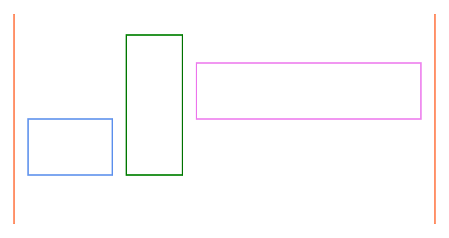
Refer to the following example code to draw a layout with simple position constraints:
// Initialize LayoutHost. This defines the origin of the coordinate system.
var host = new LayoutHost();

// Create LayoutView. This defines a rectangular region with width and height.
LayoutView view = host.CreateView(600, 300);

// Create a left vertical line by setting AnchorParam to left.
var bL = view.CreateRect();
bL.AnchorVerticalLine(null);
bL.SetLeft(null, AnchorParam.Left);

// Create a right vertical line by setting AnchorParam to right.
var bR = view.CreateRect();
bR.AnchorVerticalLine(null);
bR.SetRight(null, AnchorParam.Right);

// Create a blue rectangle and set its AnchorParam.
var r1 = view.CreateRect();
r1.SetTop(null, AnchorParam.VerticalCenter);
r1.SetWidth(120);
r1.SetHeight(80);
r1.SetLeft(bL, AnchorParam.Right, 20);

// Create a green rectangle (rotated 270 degrees or 90 degrees counterclockwise) and set its AnchorParam.
var r2 = view.CreateRect();
r2.SetAngle(r1, 270);
r2.SetLeft(r1, AnchorParam.Bottom);
r2.SetWidth(200);
r2.SetHeight(80);
r2.SetTop(r1, AnchorParam.Right, 20);

// Create a violet rectangle and set its AnchorParam.
var r3 = view.CreateRect();
r3.SetAngle(r1, 0);
r3.SetBottom(r1, AnchorParam.Top);
r3.SetHeight(80);
r3.SetLeft(r2, AnchorParam.Bottom, 20);
r3.SetRight(bR, AnchorParam.Left, -20);

// Calculate all rectangle coordinates based on the constraints provided.
host.PerformLayout();

// Draw the rectangles on a bitmap.
using var bmp = new GcBitmap((int)(view.Width + 40), (int)(view.Height + 40), true);
using var g = bmp.CreateGraphics(Color.White);
var m = Matrix3x2.CreateTranslation(20, 20);

// Draw the vertical lines and rectangles.
DrawRect(bL, Color.Coral);
DrawRect(bR, Color.Coral);
DrawRect(r1, Color.CornflowerBlue);
DrawRect(r2, Color.Green);
DrawRect(r3, Color.Violet);
void DrawRect(LayoutRect r, Color c)
{
    g.Transform = r.Transform.Multiply(m);
    g.DrawRectangle(r.AsRectF(), new Pen(c, 2));
}

// Save the image.
bmp.SaveAsPng("test2.png");
Chained Position Constraints
Chained position constraints set the parameters of a LayoutRect to fill the whole width or height of some area with multiple rectangles having different proportional sizes (measured in stars). The widths or heights of the rectangles will be proportional to their weights (number of stars). The SetLeftAndOpposite and SetBottomAndOpposite methods are used to set the chained constraints. These methods create two constraints at once.
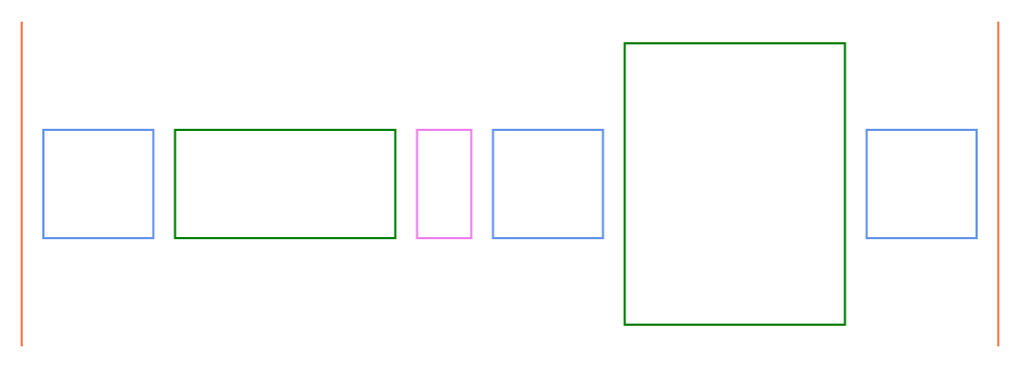
Refer to the following example code to draw a layout with chained position constraints:
// Initialize LayoutHost. This defines the origin of the coordinate system.
var host = new LayoutHost();

// Create LayoutView. This defines a rectangular region with some width and height.
LayoutView view = host.CreateView(900, 300);

// Create a left vertical line by setting AnchorParam to left.
var bL = view.CreateRect();
bL.AnchorVerticalLine(null);
bL.SetLeft(null, AnchorParam.Left);

// Create a right vertical line by setting AnchorParam to right.
var bR = view.CreateRect();
bR.AnchorVerticalLine(null);
bR.SetRight(null, AnchorParam.Right);

// Create blue, green, and violet rectangles.
var r1 = view.CreateRect();
r1.AnchorTopBottom(null, 100, 100);

var r2 = view.CreateRect();
r2.AnchorTopBottom(null, 100, 100);

var r3 = view.CreateRect();
r3.AnchorTopBottom(null, 100, 100);

var r4 = view.CreateRect();
r4.AnchorTopBottom(null, 100, 100);

var r6 = view.CreateRect();
r6.AnchorTopBottom(null, 100, 100);

// Create a green rectangle rotated 90 degrees.
var r5 = view.CreateRect();
r5.SetAngle(null, 90);
r5.SetLeft(null, AnchorParam.Top, 20);
r5.SetRight(null, AnchorParam.Bottom, -20);

// Create a chain of rectangles by setting the AnchorParam. The SetLeftAndOpposite and SetBottomAndOpposite methods are used to set chained position constraints.
r1.SetLeft(bL, AnchorParam.Right, 20);
r2.SetLeftAndOpposite(r1, AnchorParam.Right, 20);
r3.SetLeftAndOpposite(r2, AnchorParam.Right, 20);
r4.SetLeftAndOpposite(r3, AnchorParam.Right, 20);
r5.SetBottomAndOpposite(r4, AnchorParam.Right, -20);
r6.SetLeftAndOpposite(r5, AnchorParam.Top, 20);
r6.SetRight(bR, AnchorParam.Left, -20);

// Set the star and fixed widths.
r1.SetStarWidth(2);
r2.SetStarWidth(4);
r3.SetWidth(50);
r4.SetStarWidth(2);
r6.SetStarWidth(2);

// Set the star height as this rectangle is rotated.
r5.SetStarHeight(4);

// Calculate all rectangle coordinates based on the constraints provided.
host.PerformLayout();

// Draw the rectangles on a bitmap.
using var bmp = new GcBitmap((int)(view.Width + 40), (int)(view.Height + 40), true);
using var g = bmp.CreateGraphics(Color.White);
var m = Matrix3x2.CreateTranslation(20, 20);

// Draw the vertical lines and rectangles.
DrawRect(bL, Color.Coral);
DrawRect(bR, Color.Coral);
DrawRect(r1, Color.CornflowerBlue);
DrawRect(r2, Color.Green);
DrawRect(r3, Color.Violet);
DrawRect(r4, Color.CornflowerBlue);
DrawRect(r5, Color.Green);
DrawRect(r6, Color.CornflowerBlue);
void DrawRect(LayoutRect r, Color c)
{
    g.Transform = r.Transform.Multiply(m);
    g.DrawRectangle(r.AsRectF(), new Pen(c, 2));
}

// Save the image.
bmp.SaveAsPng("test3.png");
Minimum or Maximum Position Constraints
Min/Max position constraints bind a single LayoutRect parameter to one or several other LayoutRects. The AppendMinTop method is used in the following case to define the minimum top gap between the LayoutRect and other LayoutRects.
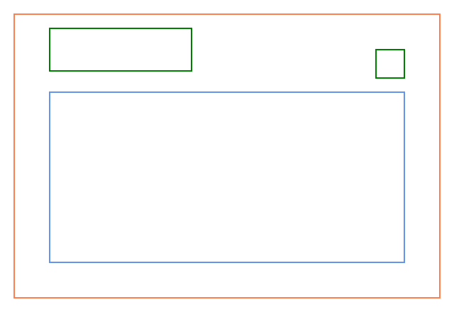
Refer to the following example code to draw a layout with minimum position constraints:
// Initialize LayoutHost. This defines the origin of the coordinate system.
var host = new LayoutHost();

// Create LayoutView. This defines a rectangular region with some width and height.
LayoutView view = host.CreateView(600, 400);

// Create an outer rectangle.
var rOuter = view.CreateRect();
rOuter.AnchorExact(null);

// Create an inner rectangle.
var rInner = view.CreateRect();
rInner.AnchorBottomLeftRight(rOuter, 50, 50, 50);

// Create rectangles.
var r1 = view.CreateRect();
r1.AnchorTopLeft(rOuter, 20, 50, 200, 60);
var r2 = view.CreateRect();
r2.AnchorTopRight(rOuter, 50, 50, 40, 40);

// Set the position of the inner rectangle according to the other rectangles.
rInner.AppendMinTop(rOuter, AnchorParam.Top, 50);
rInner.AppendMinTop(r1, AnchorParam.Bottom, 20);
rInner.AppendMinTop(r2, AnchorParam.Bottom, 20);

// Calculate all rectangle coordinates based on the constraints provided.
host.PerformLayout();

// Draw the rectangles on a bitmap.
using var bmp = new GcBitmap((int)(view.Width + 40), (int)(view.Height + 40), true);
using var g = bmp.CreateGraphics(Color.White);
var m = Matrix3x2.CreateTranslation(20, 20);

// Draw the rectangles.
DrawRect(rOuter, Color.Coral);
DrawRect(rInner, Color.CornflowerBlue);
DrawRect(r1, Color.Green);
DrawRect(r2, Color.Green);
void DrawRect(LayoutRect r, Color c)
{
    g.Transform = r.Transform.Multiply(m);
    g.DrawRectangle(r.AsRectF(), new Pen(c, 2));
}

// Save the image.
bmp.SaveAsPng("test4.png");
Anchor Points
Anchor points set the parameters of a LayoutRect relative to a LayoutView, other LayoutRects, or the special anchor points. The anchor points can be created with the CreatePoint method of a LayoutView or LayoutRect object.
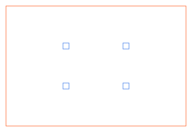
Refer to the following example code to draw a layout with anchor points:
// Initialize LayoutHost. This defines the origin of the coordinate system.
var host = new LayoutHost();

// Create LayoutView. This defines a rectangular region with some width and height.
LayoutView view = host.CreateView(600, 400);

// Create main rectangle.
var rMain = view.CreateRect();
rMain.AnchorExact(null);

// Create anchor points.
var ap1 = rMain.CreatePoint(1f / 3, 1f / 3);
var ap2 = rMain.CreatePoint(2f / 3, 1f / 3);
var ap3 = rMain.CreatePoint(1f / 3, 2f / 3);
var ap4 = rMain.CreatePoint(2f / 3, 2f / 3);

// Create four rectangles and position them as per the anchor points defined.
var r1 = view.CreateRect();
AnchorCenter(r1, ap1);
var r2 = view.CreateRect();
AnchorCenter(r2, ap2);
var r3 = view.CreateRect();
AnchorCenter(r3, ap3);
var r4 = view.CreateRect();
AnchorCenter(r4, ap4);
void AnchorCenter(LayoutRect r, AnchorPoint ap)
{
    r.SetHorizontalCenter(ap);
    r.SetVerticalCenter(ap);
    r.SetWidth(20);
    r.SetHeight(20);
}

// Calculate all rectangle coordinates based on the constraints provided.
host.PerformLayout();

// Draw the rectangles on a bitmap.
using var bmp = new GcBitmap((int)(view.Width + 40), (int)(view.Height + 40), true);
using var g = bmp.CreateGraphics(Color.White);
var m = Matrix3x2.CreateTranslation(20, 20);

// Draw the rectangles.
DrawRect(rMain, Color.Coral);
DrawRect(r1, Color.CornflowerBlue);
DrawRect(r2, Color.CornflowerBlue);
DrawRect(r3, Color.CornflowerBlue);
DrawRect(r4, Color.CornflowerBlue);
void DrawRect(LayoutRect r, Color c)
{
    g.Transform = r.Transform.Multiply(m);
    g.DrawRectangle(r.AsRectF(), new Pen(c, 2));
}

// Save the image.
bmp.SaveAsPng("test5.png");
Constraints based on other LayoutView
The LayoutRect parameters cannot be bound to a LayoutRect from another LayoutView. However, it is possible to bind parameters to any anchor point within the same LayoutHost.
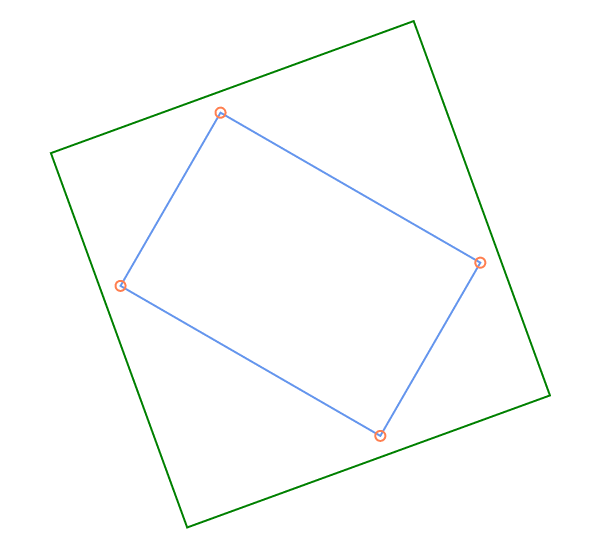
Refer to the following example code to draw a layout circumscribed in a layout from another LayoutView:
// Initialize LayoutHost. This defines the origin of the coordinate system.
var host = new LayoutHost();

//Create rotation.
const double DegToRad = Math.PI / 180;
var m1 = Matrix.CreateRotation(DegToRad * 30);
m1 = m1.Translate(190, -50);

// Create first view and rectangle.
var view1 = host.CreateView(10, 10, m1);
var rc1 = view1.CreateRect();
rc1.AnchorTopLeft(null, 30, 30, 300, 200);

// Create second view and rectangle.
var m2 = Matrix.CreateRotation(DegToRad * -20);
var view2 = host.CreateView(10, 10, m2);
var rc2 = view2.CreateRect();

// Create anchor points.
var ap1 = rc1.CreatePoint(0, 0);
var ap2 = rc1.CreatePoint(1, 0);
var ap3 = rc1.CreatePoint(1, 1);
var ap4 = rc1.CreatePoint(0, 1);

// Add constraints relative to the anchor points.
rc2.SetTop(ap1, -20);
rc2.SetBottom(ap3, 20);
rc2.SetLeft(ap4, -20);
rc2.SetRight(ap2, 20);

// Calculate all rectangle coordinates based on the constraints provided.
host.PerformLayout();

// Draw the rectangles and ellipses on a bitmap.
using var bmp = new GcBitmap(600, 550, true);
using var g = bmp.CreateGraphics(Color.White);
var m = Matrix3x2.CreateTranslation(20, 20);

// Draw the rectangles and ellipses.
DrawRect(rc1, Color.CornflowerBlue);
DrawRect(rc2, Color.Green);
DrawPoint(ap1);
DrawPoint(ap2);
DrawPoint(ap3);
DrawPoint(ap4);
void DrawRect(LayoutRect r, Color c)
{
    g.Transform = r.Transform.Multiply(m);
    g.DrawRectangle(r.AsRectF(), new Pen(c, 2));
}
void DrawPoint(AnchorPoint ap)
{
    g.Transform = ap.Transform.Multiply(m);
    g.DrawEllipse(new RectangleF(-5, -5, 10, 10), new Pen(Color.Coral, 2));
}

// Save the image.
bmp.SaveAsPng("test6.png");
Dependent Views and Transformations
The hierarchy of LayoutViews is not necessarily flat within the same LayoutHost. Some views can be nested in other views. When the transformation matrix of the parent LayoutView is updated, all child view transformations are recalculated.
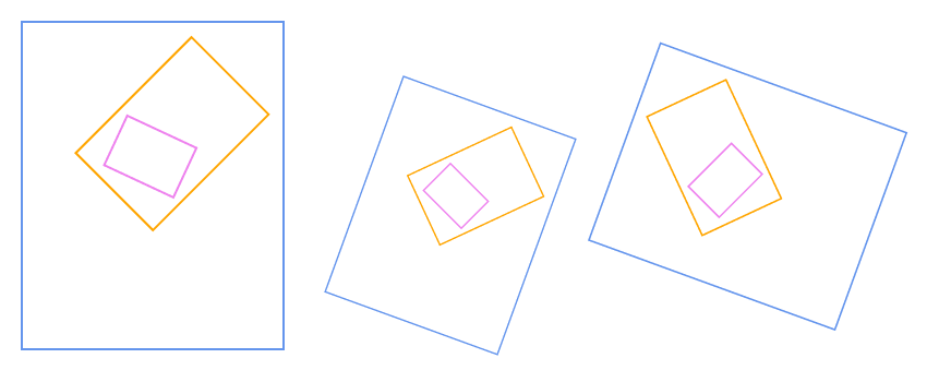
// Initialize LayoutHost. This defines the origin of the coordinate system.
var host = new LayoutHost();

// Create first view and rectangle.
var view1 = host.CreateView(240, 300);
var rc1 = view1.CreateRect();
rc1.AnchorExact(null);

// Create second view and rectangle.
var view2 = host.CreateView(100, 150);
var rc2 = view2.CreateRect();
rc2.AnchorExact(null);

// Create third view and rectangle.
var view3 = host.CreateView(70, 50);
var rc3 = view3.CreateRect();
rc3.AnchorExact(null);

//Create rotation.
const double DegToRad = Math.PI / 180;
var m2 = Matrix.CreateRotation(DegToRad * 45);
view2.SetRelativeTransform(view1, m2.Translate(120, -100));
var m3 = Matrix.CreateRotation(DegToRad * -20);
view3.SetRelativeTransform(view2, m3.Translate(-23, 90));

// Calculate all rectangle coordinates based on the constraints provided.
host.PerformLayout();

// Draw the rectangles on a bitmap.
using var bmp = new GcBitmap(850, 350, true);
using var g = bmp.CreateGraphics(Color.White);

// Draw the first set of rectangles according to the first transformation matrix.
var m = Matrix3x2.CreateTranslation(20, 20);
DrawRect(rc1, Color.CornflowerBlue);
DrawRect(rc2, Color.Orange);
DrawRect(rc3, Color.Violet);

// Draw the second set of rectangles according to the second transformation matrix.
view1.Transform = Matrix.CreateTranslation(350, 50).Scale(0.7).Rotate(DegToRad * 20);
host.PerformLayout();
DrawRect(rc1, Color.CornflowerBlue);
DrawRect(rc2, Color.Orange);
DrawRect(rc3, Color.Violet);

// Draw the third set of rectangles according to the third transformation matrix.
view1.Transform = Matrix.CreateTranslation(520, 200).Scale(0.8).Rotate(DegToRad * -70);
host.PerformLayout();
DrawRect(rc1, Color.CornflowerBlue);
DrawRect(rc2, Color.Orange);
DrawRect(rc3, Color.Violet);
void DrawRect(LayoutRect r, Color c)
{
    g.Transform = r.Transform.Multiply(m);
    g.DrawRectangle(r.AsRectF(), new Pen(c, 2));
}

// Save the image.
bmp.SaveAsPng("test7.png");
Contours
Contour is a closed figure drawn through anchor points. One side of a LayoutRect can be bound to one or several contours. From LayoutRect’s point of view, contours consist of the outer area, the inner area, and the border area. Rectangles can be bound to positions where one area changes to another. The CreateContour method of LayoutView class creates an object of Contour class, which is used to draw a contour.
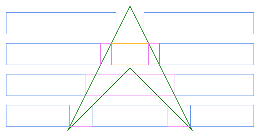
// Initialize LayoutHost. This defines the origin of the coordinate system.
var host = new LayoutHost();

// Create LayoutView. This defines a rectangular region with some width and height.
LayoutView view = host.CreateView(800, 400);

// Create a contour.
var contour = view.CreateContour();
contour.AddPoints(new AnchorPoint[]
{
    view.CreatePoint(0, 0, 400, 0),
    view.CreatePoint(0, 0, 600, 400),
    view.CreatePoint(0, 0, 400, 200),
    view.CreatePoint(0, 0, 200, 400)
});

// Create first row of rectangles.
var rc11 = view.CreateRect();
rc11.AnchorLeftTopBottom(null, 0, 20, 310);
rc11.AppendMaxRight(contour, ContourPosition.FirstInOutside);
var rc12 = view.CreateRect();
rc12.AnchorRightTopBottom(null, 0, 20, 310);
rc12.AppendMinLeft(contour, ContourPosition.FirstInOutside);

// Create second row of rectangles.
var rc21 = view.CreateRect();
rc21.AnchorLeftTopBottom(null, 0, 120, 210);
rc21.AppendMaxRight(contour, ContourPosition.FirstInOutside);
var rc22 = view.CreateRect();
rc22.AnchorTopBottom(null, 120, 210);
rc22.SetLeft(rc21, AnchorParam.Right);
rc22.AppendMaxRight(contour, ContourPosition.FirstInInside);
var rc23 = view.CreateRect();
rc23.AnchorTopBottom(null, 120, 210);
rc23.SetLeft(rc22, AnchorParam.Right);
rc23.AppendMaxRight(contour, ContourPosition.NextOutInside);
var rc24 = view.CreateRect();
rc24.AnchorTopBottom(null, 120, 210);
rc24.SetLeft(rc23, AnchorParam.Right);
rc24.AppendMaxRight(contour, ContourPosition.NextOutOutside);
var rc25 = view.CreateRect();
rc25.SetLeft(rc24, AnchorParam.Right);
rc25.AnchorRightTopBottom(null, 0, 120, 210);

// Create third row of rectangles.
var rc31 = view.CreateRect();
rc31.AnchorRightTopBottom(null, 0, 220, 110);
rc31.AppendMinLeft(contour, ContourPosition.FirstInOutside);
var rc32 = view.CreateRect();
rc32.AnchorTopBottom(null, 220, 110);
rc32.SetRight(rc31, AnchorParam.Left);
rc32.AppendMinLeft(contour, ContourPosition.LastOutOutside);
var rc33 = view.CreateRect();
rc33.SetRight(rc32, AnchorParam.Left);
rc33.AnchorLeftTopBottom(null, 0, 220, 110);

// Create fourth row of rectangles.
var rc41 = view.CreateRect();
rc41.AnchorLeftTopBottom(null, 0, 320, 10);
rc41.AppendMaxRight(contour, ContourPosition.FirstInOutside);
var rc42 = view.CreateRect();
rc42.AnchorTopBottom(null, 320, 10);
rc42.SetLeft(rc41, AnchorParam.Right);
rc42.AppendMaxRight(contour, ContourPosition.NextOutOutside);
var rc43 = view.CreateRect();
rc43.AnchorTopBottom(null, 320, 10);
rc43.SetLeft(rc42, AnchorParam.Right);
rc43.AppendMaxRight(contour, ContourPosition.FirstInOutside);
var rc44 = view.CreateRect();
rc44.AnchorTopBottom(null, 320, 10);
rc44.SetLeft(rc43, AnchorParam.Right);
rc44.AppendMaxRight(contour, ContourPosition.NextOutOutside);
var rc45 = view.CreateRect();
rc45.SetLeft(rc44, AnchorParam.Right);
rc45.AnchorRightTopBottom(null, 0, 320, 10);

// Calculate all rectangle coordinates based on the constraints provided.
host.PerformLayout();

// Draw the rectangles and contour on a bitmap.
using var bmp = new GcBitmap((int)(view.Width + 40), (int)(view.Height + 40), true);
using var g = bmp.CreateGraphics(Color.White);
var m = Matrix3x2.CreateTranslation(20, 20);
g.Transform = m;

// Draw the rectangles and contour.
DrawContour(contour);
DrawRect(rc11, Color.CornflowerBlue);
DrawRect(rc12, Color.CornflowerBlue);
DrawRect(rc21, Color.CornflowerBlue);
DrawRect(rc22, Color.Violet);
DrawRect(rc23, Color.Orange);
DrawRect(rc24, Color.Violet);
DrawRect(rc25, Color.CornflowerBlue);
DrawRect(rc31, Color.CornflowerBlue);
DrawRect(rc32, Color.Violet);
DrawRect(rc33, Color.CornflowerBlue);
DrawRect(rc41, Color.CornflowerBlue);
DrawRect(rc42, Color.Violet);
DrawRect(rc43, Color.CornflowerBlue);
DrawRect(rc44, Color.Violet);
DrawRect(rc45, Color.CornflowerBlue);
void DrawContour(Contour co)
{
    var pts = co.Points.Select(ap => ap.TransformedLocation).ToArray();
    g.DrawPolygon(pts, new Pen(Color.Green, 2));
}
void DrawRect(LayoutRect r, Color c)
{
    g.Transform = r.Transform.Multiply(m);
    g.DrawRectangle(r.AsRectF(), new Pen(c, 2));
}

// Save the image.
bmp.SaveAsPng("test8.png");

